Electric-Piano-using-555-Timer-IC
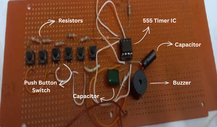
Fig 1: Circuit Image
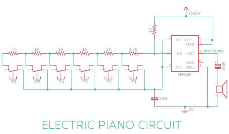
Fig 2: Circuit Diagram
Project Overview
This is a classic electronics mini-project that demonstrates the principles of frequency modulation and sound generation. By configuring the 555 Timer IC in astable multivibrator mode, the circuit produces distinct musical notes suitable for a mini piano.
Components Required
- IC: NE555 Timer.
- Output: 8-ohm Speaker (0.5W).
- Power: 9V DC Battery.
- Control: 5-8 Push Buttons (Tactile switches).
- Passive: Resistors (various values) & Capacitors.
Circuit Principle
The 555 timer is set up in Astable Mode, meaning it generates a continuous square wave pulse. The frequency of this wave determines the "pitch" of the sound.
Formula: f = 1.44 / ((R1 + 2*R2) * C)
When different buttons are pressed, different resistors are added to the circuit. This changes the value of R2 in the formula, altering the frequency and creating different musical tones (Do, Re, Mi, etc.).
Key Features
- Low-cost implementation.
- Practical demonstration of RC charging/discharging cycles.
- Adjustable tone frequency based on resistor selection.